

A trite phrase sprang up in southern California in the late 1960's following the introduction of the fuel injected flat fours. "There's only two kinds of Volkswagens: Those that have had an engine fire and those that are about to." But the odd thing was, veedubs have always had engine fires, and in the case of the bugs and buses, the cause was almost always the same.
In over 90% of early VW engine fires (*) the steel fuel line breaks where it passes through the breast tin on the driver's side of the engine compartment. The broken line dumps fuel directly onto the neck of the #3 exhaust outlet. The rest is history. Once the fuel line breaks, gravity keeps the fuel flowing to the fire. When the magnesium tranny housing heats to the point of ignition, even water can't put it out.
Why does the fuel line break? Because of the failure of the rubber grommet where the steel fuel line passes through the forward breast tin. Located only inches away from the the #3 exhaust stack, which runs red hot, the grommet soon hardens. Vibration does the rest, first crumbling the grommet then providing the motion that allows the breast tin to cut through the steel tubing like a hacksaw. A dull and toothless hacksaw but one that cuts a lot faster than you would think. This scenario of component failure and wear is generally known as The Engine Fire Syndrome.
The fix? Make a bulkhead fitting.
You can make a bulkhead fitting that's good enough for the job using lamp repair parts, purchased at a hardware store. The light socket is attached to the lamp by a piece of threaded 3/8" steel or brass tubing. The threaded tubing is widely available, often sold bubble-packed in an assortment of lengths. You need a piece about an inch long. Matching nuts are sold the same way, they are usually hanging side-by-side among the other lamp repair parts. You will also need a pair of flat washers with a 3/8" center hole. Be sure the washers are large enough to cover the hole in the breast tin. Fender washers work best but you'll have to drill them out to pass the threaded tubing.
Assemble the parts so as to sandwich the breast tin between the two washers. To make sure it doesn't come apart, bed the washers and nuts in high-temperature RTV compound. It's messy but I've found this is the only assembly method that stands up over the years.
In proper terms, what you end up with isn't a bulkhead fitting but a pass-through. And what you pass through it is a piece of 5mm steel fuel line (that is, regular VW fuel pipe) about three inches long. Bed this in RTV as you insert it into the threaded sleeve with a twisting motion (but don't get any in the fuel line). NOW you have a bulkhead fitting. Use regular push-on fuel line (but with clamps, please) to connect to the bulkhead fitting and you're all done.
The Engine Fire Syndrome was first identified about 1958. Despite frequent fires, VW showed no interest in fixing the problem, insisting the lame rubber grommet they used was good enough so long as someone inspected/replaced it every 3,000 miles or so(!), which they did, back when there was a VW dealer in every town and service was cheap.
Making a bulkhead fitting from commonly available parts will prevent a lot of engine fires but the fuel system on early Volkswagens remains a compromise between safety and cost. Having invested considerable time and money keeping our bugs alive, it seems silly to put that investment at risk by using push-on fuel lines. Threaded aircraft-type fittings are a better solution; the carb and fuel pump can be modified to accept such fittings. Using a true bulkhead fitting through the forward breast tin, and braided stainless steel flex lines between there and the carb, will give you the safest possible installation.
If you're serious about safety and long-term durability, you may wish to carry the fuel line modifications all the way through to the gas tank, even to replacing the fuel pipe in the center hump with stainless steel tubing. This is best accomplished during a body-off resto. Once things are back together you'll know your fuel system will never fail.
A neat trick that gets around the difficulties of replacing tubing in the center hump is to run a new 3/8" diameter stainless steel fuel line externally. It is protected by a piece of 3/4" angle iron welded to the belly pan in the form of a 'V'. A bit of artful grinding and some careful bending allows the angle iron stock to follow the contours of the belly pan stampings. Tacked and then welded full-length, the modification is strong, attractive and durable.
I've been working on VWs since 1956 and have seen, personally or in photos, the results of several fires as described above. The cause of the fire was often overlooked because the steel fuel line appears to be intact. But on cleaning away the fire's residue you'll discover the tube is cut half through, which for a fuel pipe is as far as you need go to make the juice flow.
(*) That was then. Nowadays VW owners have come up with an even easier method of setting their cars on fire. How? By simply adding an after-market fuel-filter to the rubber hose between the fuel pump an the carb. Over time, the vibration due to the added mass of the fuel-filter causes the brass ferules in the fuel pump and carb to loosen. Once they come loose, the engine is bathed in gasoline and another bug or bus becomes history. Fortunately, it's easy to fix and the procedure is included in this collection. -rsh, 2006
Friday, November 24, 2006
VW - Jugs

(The following was in response to a Vintage VW List subscriber who was given an engine for free. Unfortunately, the engine was a POS with near-zero compression. The fellow wondered if he could simply replace the rings and make a quick sale.)
I'll tell you one thing that don't work. Doing a ring-job on a VW. The fixture to properly hone a VW jug is the size of a milling machine. I think there are two of them in southern California, which could well mean two of them in the whole damn country. The problem is returning the cast iron jug to a perfect circle AT OPERATING TEMPERATURE, close enough to the OD of available pistons to be sealed by available piston rings. To do this, the jug has to be distorted at room temperature to take into account their variable wall thickness (ie, the stud channels in the fins). VW stopped re-manufacturing jugs in the '60's, having found it impossible to equal the service life of new jugs at an economic cost.
If a set of jugs has less than 2,000 miles on them I might hone them and put in new rings. Otherwise, I scrap them. In the long run, it's cheaper.
If your 'free' engine has honed jugs, scrap them.
Jugs in General
First thing you do with a set of new jugs is wash them with clean mineral spirits. (Okay, gasoline, but don't get caught.) When they are perfectly, absolutely oil-free, take a cheap 1/2" paint brush and turn it into a 1/4" paint brush by cutting off half the bristles at the ferrule. That's what you need to get paint down into the bottom of the fins.
Now paint those puppies! Thin coat, please. Flat black Rustoleum in the can, not the spray stuff. Thin it out a little. Do a neat job of it; don't get any paint in the bores or the spigot sleeve, and keep paint off the sealing surfaces. (I didn't say it was easy.)
Let them harden up a couple of days. Inspect for holidays, touch them up. If you don't paint them, they won't last the twenty years and more they can last, when you're running a full-flow oil filter.
Once they are painted get a can of Bon Ami cleanser and scrub the bores. That pretty swirl pattern contains microscopic fragments of carborundum! It is embedded into the soft iron granules that are part of the matrix of cast iron, which unlike mild steel is far from homogeneous. Spend about twenty minutes scrubbing each jug. Use a sponge and lots of cleanser but not too much water. Scrub around the bore, not up and down. When you get done, give them a good hot water rinse, and I mean too hot to touch. Get the whole cylinder hot. Wipe them with a known-clean rag or towel. Spray the bore immediately with WD-40 (a San Diego product, by the way and a nice stock to own) and put them in a warm oven or drying box (ie, light bulb in a cabinet) to insure all moisture is driven out. When dry, you can oil them lightly and bag them, or store them back in their box if the cardboard is dry.
The hour or so you spend scrubbing your jugs adds about a year to their useful life but more importantly, saves you several hundred dollars in oil over the life of the engine. Those microscopic bits of carborundum come from the manufacturing process and will remain in the jugs, being polished deeper into the walls or taken up by the rings, unless you remove them. The pumice and diatomatious earth used in Bon Ami brand cleanser has a hardness of about 4 on the Mohs scale. Carborundum is 9+, right up there with bort, industrial grade diamond. It don't go away. Cast iron is harder than pumice or diatomatious earth, they do go away. Indeed, if you do a good job, there won't be any for the engine to flush away.
So why do people leave abrasives in engines? Because it lets the rings wear in almost instantly. If you're building engines on an assembly line, it is a justified compromise. Jugs on aircraft engines are cleaned with a series of hand-scrubbings and ultrasonics. They can last about 4,000 hours before catastrophic failure (which is why they are normally overhauled at about 2,000 hours). 4,000 hours on a Lycoming is the equivalent of about 300,000 miles on a in a VW.
(So why don't we use ultrasonics and all that high-tech stuff on veedubs? Some guys do! But the main reason is practicality. Your main bearings dictate the maximum useful life of your engine and right now, they're only good for about 150,000: they lack the surface area to survive longer. And it makes no sense to put 300,000 mile jugs on a 150,000 mile engine. The hidden lesson here is that engines are harmonious things, their parts work -- and wear -- in concert. Put new, tight jugs on a worn lower end and the poor thing won't last a year. Even worse, it's liable to suffer a catastrophic rod-bearing failure. But when new parts wear-in together they will give you plenty of warning as the end of their useful life approaches.)
No, you can't use that can of Comet under the sink. It contains chlorine, something you don't want anywhere near cast iron. And don't worry about the rings seating. Follow the break-in procedure I mentioned; don't be afraid to rev that puppy up. (Think of it as birthing pains.)
Basic Jugs
A set of VW jugs includes new pistons, pins & rings.
First thing you do, you sit down with one piston, take the rings off one at a time, make a sketch of its profile, mark down if its the top or middle ring, which side up, etc. You'll see lots of different types so don't put your faith in a book. Use the set you have as your book.
Make a good drawing. Keep it clean. Keep it in a notebook and the notebook in a drawer. It's like a penny savings account. You think it's just pocket change but when you need it, it turns out to be a lifesaver.
End gap should be okay but it only takes a couple minutes to check the whole set and you've got to take them apart anyway for balancing, cleaning, etc. So check the gap. Keep the rings together by sets; put them into baggies with a paper tag telling what piston they came off of. Mark the pistons clearly, either with a scribe or a punch. Mark the jugs too -- sometimes you find a wild one in a set, a couple thou larger or smaller than the others, with rings gapped to match. At the factory, they dealt with thousands of jugs from conscientious suppliers. Aftermarket stuff runs from junk to sublime, you have to decided what you've got.
Big Bore
Boring subject. Big bore means opening up the case to accept larger spigots. Type IV is 100mm and up. Biggest practical bore on regular bug engine is 94 for a late case, 92 for early (and they'll still leak), in the real world don't go over 88 & 90 (old & new). It has to do with the compression seal and how much 'shelf' space is left after you open up the bore. The jug has to seat on a flat, parallel surface to insure no oil leaks, fretting, etc between jug and case. Open the case too much, not enough sealing surface, engine goes to hell. And not just from leaks. There are purely mechanical considerations here as well. The total stress of jugs, studs & heads is concentrated at the base of the jugs. The jugs will pound into the case during the first five-six hours of running. Smart builders do it on a test stand, dismantle tin, re-torque. Do it again about 50,000 miles, maybe pull the heads then, too. Don't gasket the jug/case joint, use Permatex, the non-hardening kind (light tan?) or that new gray RTV gasket stuff. Paper gasket is a joke between cast iron & magnesium subject to heat cycles (as VW learned). Best builders O-ring the spigot bores. Tricky to do (needs special tooling) but works like a dream. (See Larry Pauter's all-billet aluminum cases. About six grand each.)
J.C.Whitney Big Bores
I've never bought any from them. I've seen too many different brands, too many unbalanceable sets. You're going to have to trust to luck and understand it's on your shoulders. That's why balancing becomes so important. You are not just assembling an engine, you are manufacturing it.
If the things claim to be Big Bore but also say they don't require machining the case, walk on by. The biggest stock bore was 85.5mm. The only way you can fit a bigger jug into the stock spigot hole is to make the skirt and cylinder wall thinner. Thin sections of cast iron don't do well when subjected to rapid heat cycling. Such 'big bore' jugs distort, leading to sealing problems and uneven wear. They certainly don't hold up as well as their heavier walled cousins.
Standard Size Jugs
Regular jugs have stricter standards in both material and workmanship. I'd be more willing to try a mail-order set of standard jugs. I've a hunch the odds would be on the side of getting better quality than the so-called Big Bore things.
(After dismantling the free engine and finding the cam was off by a couple of teeth, he wondered if he could simply button it back up without replacing the jugs, balancing, or replacing the exhaust valves & guides.)
Run What ya' Brung!
Sure, it'll run. Might even last a year or two if you're careful. But it won't be sweet. Its life is 90% over before you begin. If your only option is to sell the thing to a kid, I guess that's the way to go. But you must understand that once you touch something with a wrench you own it. First sign of trouble, the kid's going to come knocking on your door. Or maybe his dad. Have that thing sitting out in the drive, dripping oil, swallowing a quart a hundred and blowing smoke all over town, everybody knows. At least, all the mechanics do. (Big scarlet 'M' sewn to your shirt? Same thing.)
Unless you're all packed and ready to move I think it would make real good sense to build the best engine you can, make sure the buyer understands any corners you've had to cut and the down- stream consequences. Do a good job, it's going to be around for a long time. And every time people see it some of them will remember who built the engine.
Come on! A week ago you didn't have a spare engine, now you do. Make it the best engine you can build. Every engine will teach you something; every engine will instill habits. You want to learn the good habits, have them teach you the right stuff. And none of the really good mechanics die rich.
-Bob
VW - Auto Shop 101
I'm over at Pacific Bugs and there's a bunch of kids wetting themselves around this bitchin' sano slammed '68 bus, the one with no hatch on the engine compartment so everyone can admire the chrome. Chrome everything. The kid has even chromed the wires fer crysakes!
I go in, get the gaskets I came for, come out. The kid who owns the bus is instructing his loyal subjects on Engineering Reality. "You don't need that spring," he says, "...because the distributor is only turning at one-fourth engine speed."
"Wrong." I shoulda kept my mouth shut but American kids are already too dumb to pour piss out of a boot.
Stunned silence. Their Master has been Challenged. And by some geezer in a greasy ol' cap driving a Toyota, yet.
I started to say something then let it go, open the door of the truck. Ignorance is bliss. And the more veedubs the kiddies screw up, the more business for all those busy little VW mechanics.
"Excuse me, sir," very snotty. "But the air-cooled Volkswagen engine is a four-stroke engine," the Master Mechanic sez, real cool, little grin. "And the distributor turns at..."
I sigh, shake my head. "Wrong again. Four cycles, not four strokes. Otto-cycle engine uses two strokes, four cycles. And the distributor turns at half engine speed, not a quarter. Go count the teeth on the gears."
Confusion ripples across a half-dozen pimply faces. Gears? Teeth? I climb into the truck, fire it up, back out. "And you need the little spring because I say you do, so put the sonofabitch back in." Hard stare at the Master Mechanic. He blinks and I drive off. The kids gape after me.
I've no idea what spring he was talking about. Being omnipotent isn't as easy as it looks.
Bob
VW - Baja Firewood Kit & Cooking Instructions
.
A Baja Firewood Kit consists of a pair of heavy leather gloves. Heavy as in thick -- the kind used to handle hot steel. Plus a piece of light line eight to ten feet long.
Make the length of line into a loop and fasten the ends with a square knot. This is what you carry your firewood in.
Go looking for firewood. It will be laying on the ground. Most of it isn't much larger than twigs. It will have thorns -- hence the gloves. As you collect each piece, tap it on the ground -- gets rid of hitch-hikers. When you've collected a handful, put it into your rope sling, passing the loop through itself and grasping it where it draws up on the bundle.
Keep looking. When your bundle is about two feet in diameter, head back toward camp, still looking.
When you have a bundle about three feet in diameter you'll run out of rope -- you're all done.
This sort of firewood is often called 'squaw wood' meaning stuff anyone can pick up -- no ax needed. The stuff burns up fast. To learn to live with this kind of fuel-source you have to break the bon-fire habit -- keep your fire no bigger than a frying pan. The usual routine is to dig a little trench, curb it with a couple of rocks to hold your grill or pan, keep the fire -- a small one -- in the trench. This is a cooking fire, not a TV-Boyscout-Who's got the weanies kind of fire. Move it away from the camp. There won't be any coals to speak of. You have to tend this kind of fire constantly, feeding it a twig at a time. If you plan on keeping yourself fed, learn to use a Dutch oven. Dutch oven got legs and the lid has an inverted rim. You stand it over your fire-pit then shovel coals on top of it. If you don't have any coals you build a second small fire on top of the oven. You can cook up rabbit, quail, snake and so on in about half an hour --- and use up nearly all of a three-foot bundle of brush.
On the Pacific beaches you can usually find driftwood but you'll still need twigs and small stuff for kindling. A bow-saw is generally handier than an ax when it comes to collecting real firewood. (An ax is mostly for splitting or notching. Saws are for felling and cutting-up.)
You generally do your cooking while it's still daylight. You can't prepare a proper meal without proper light but the desert comes alive at night. A light bright enough to cook by will attract everything from bugs to bandits and that isn't a joke.
You can cook beans and stews in stages -- use up your morning firewood, insulate the Dutch oven and carry it with you -- continue cooking it that evening. So long as it's still hot, it's still cooking. Ironing board covers make handy insulators. You want a real thick pad to sit the thing on plus a sort of cap like a tea cozy, big enough to completely cover your Dutch oven or other lided kettle -- with the lid fastened down. You can sew the cozy with fiberglas thread or even safety-wire -- it doesn't have to be pretty to work.
People often overlook beans as camping fare because they take so long to cook. Fact is, beans don't take as long to cook as people think. The secret is to not cook too many at one time, and to soak them good -- right up to the point of sprouting -- before cooking.
While it's best to do your cooking during daylight, once it's cooked you can heat it up after dark -- just wait for it to start smoking. ("What's that funny smell?" "Supper.")
And if all this sounds ridiculously labor-intensive, it is. Get yourself a Coleman or Primus. Do your cooking standing up.
Stuff grows all year 'round down in Baja, especially down near the cape. (They've got some huge organic farms south of Todos Santos to keep the hotels supplied with everything from strawberries to coconuts.) Get up early, so as to catch the local market, you can usually find some roasting ears. Fresh corn goes great with fresh fish.
-Bob
VW - Free Horsepower
(written about 1995)
A subscriber of this list recently took me to task for my repeated use of the expression ‘properly assembled engine,’ insisting that some ‘shade tree mechanic from California’ could not possibly improve on Volkswagen’s own methods and their millions of engine’s-worth of experience.
He failed to consider the fact that I build just one engine at a time. And where VW specifies an acceptable range of tolerance in their parts, a necessity for high-volume production, I don’t have that particular burden. When setting crankshaft end-play, for example, I dress the thrust-face of the #1 bearing until I achieve a clearance of .0025 exactly. This takes as long as it takes, from a few minutes to a day or more if I have to track down another set of bearings. And I didn’t learn this out of books, I learned it from VW mechanics; guys who took considerable pride in being able to improve on a ‘factory job’.
What remarkable improvement in horsepower or longevity results from assembling an engine to better than factory spec? In the case of crankshaft end-play, I doubt if there’s any at all but the truth is, I don’t really care. I know that if all the shims are dead flat, the flywheel and crank are true and the thrust surface of the bearing brought to truth with dye and judicious flatting, I get a nicer fit that holds spec longer. (The wear limit here is .006; you can check it without dismantling your engine by taking the measurement from the pulley-end of the crank. It’s a quick check on the general state of health of the lower end.) No quotas. No time clocks. When it’s right, the engine tells me so. And I derive great satisfaction from that. This applies to fitting the rods, adjusting ring-gap -- to everything involved in ‘proper’ assembly of an engine. And you can do it too.
Chances are, if you’ve never built an engine before, you won’t do any worse a job of it than Volkswagen and may do even better, which is why I think everyone should build their own engines. But most of you don’t. A lot of you are satisfied with a short-block from a reputable manufacturer. And that can be a costly mistake.
Back when the Volkswagen engine was designed, the importance of balancing, both dynamic and volumetric, was not well understood; by modern standards the VW balancing specs are quite crude. The best proof of this is to compare the output of a properly assembled engine against one assembled to stock specs. The difference is never less than a 5% increase in horsepower and often as much as 10% when careful attention is given to proper balance. This shows up as improved efficiency, with the balanced engine requiring less fuel for the same output, and producing less heat. The balanced engine also lasts longer.
To properly (there’s that word again!) balance an engine the clutch pressure plate, flywheel, crankshaft (with the cam gear installed), and fan pulley are balanced as a unit. This cannot be done with a short-block without dismantling the engine. In effect, each time you elect to use a short-block you are accepting the fact the engine will not be as efficient as it could be. Another burden I escape by building one engine at a time is that I can do as many pre-assemblies as I feel are necessary; VW puts each engine together once, as does all of the high-volume after-market engine builders I know of.
With new parts, held to a reasonable tolerance and assembled -- one time -- with reasonable care, the finished product will be no worse than the stack-up of those tolerances. You could get a real dog. But tolerance stack-ups tend to cancel themselves out, which puts the odds in your favor. Even so, I prefer not to play the odds when it comes to engine assembly. Poker, yes; but with engines I’ll cheat until I get it right.
Getting the volumetric balance right is something VW would rather not talk about since they don’t time all four cylinders to fire at the same point of rotation. Even an engine with perfect volumetric balance will be out of balance when the #3 cylinder is timed to fire 4 degrees later than its three brothers. (Delaying the timing of #3 cylinder was Volkswagens solution to the chronic overheating caused by the internal oil cooler.) (Ed. Note: That ended with the introduction of the doghouse oil cooler. Without the internal oil cooler to block the flow of air to #3, Volkswagen was able to do away with the retardation.)
Volumetric balance means all of the cylinders have the same internal volume, meaning each will have exactly the same compression ratio and will deliver the same specific impulse when the spark plug fires, assuming they fire at the same degree of rotation. In theory, this isn’t very important if the engine is designed to operate at slow speeds and has a massy flywheel. In practice, the difference is as I’ve stated above. It is quite common to achieve an overall 10% gain in horsepower by properly assembling the Volkswagen engine. No tricks and no add-ons.
Volumetric balance starts with the heads. Their chamber volumes must match. In practice, you increase the volume of the three smaller chambers to match that of the largest. You do this by re-seating the valves and removing metal from the chamber by burnishing, grinding and polishing. (As a matter of course, all chambers are polished mirror-bright using a felt hob and polishing compound.) With the combustion chamber volume known, the crankcase is then assembled and the deck height measured. Cylinder spacers are used to arrive at a standard height, chosen according to the desired compression ratio. The final adjustment to a ‘fat’ cylinder may be made by shaving the head of the piston by up to .005", all other adjustments made by grinding the cylinder spacers, if needed. (Cylinder spacers are available in a wide range of thicknesses for all cylinder diameters.)
When measuring deck height it’s important that the engine be properly torqued, including heavy plates used to simulate the heads. The plate is usually cast iron or precision ground cast aluminum plate, 1/2" to 3/4" thick, pierced for use of a depth gauge; usually a dial indicator. Steel spacers, their ends machined square, are used to take up the different length of the head studs. (Sections of water pipe are perfectly adequate.)
After deck height is determined, the pistons and rods may be balanced. Rods and pistons are statically balanced; the rods are balanced so as to have a common center of mass (i.e., big-end vs little-end balancing).
Sounds pretty sexy, eh? Lots of exotic tools? Frankly, no. You can cc your heads with a turkey baster. And the polished cast plate I used to make my deck-height fixtures cost $4.20 at a scrap yard. The dial indicator is the same one I use for determining end-play, runout, cam lift and so on. The head-work is done with a standard kit of Cratex tools, common stuff to anyone who has ported or polished a head. (about $24 from Enco)
But dynamic balancing can be expensive. I use a guy who does only racing and aircraft engines; his minimum spec is an order of magnitude better than VW spec and he charges accordingly. A regular automotive engine balancer usually charges between $50 and $75, depending on where you live. Their typical spec will be much better than the VW factory spec. For example, within a set of four stock connecting rods the weight variation can be 8 grams (580-588). That’s ‘low-spec’ for VW rods. (VW does not have a spec for center of balance (i.e., center of mass; big-end vs small-end).) A set of balanced rods will vary no more than .01 gram, and their center of mass will fall within .005" of the same point. (‘Balanced’ rods from an after-market source usually means they’ll meet the minimum VW spec, which is to say they are not balanced, in modern-day terms. Buy the best rods you can afford [SIR offers good value] then have them balanced.) If you’re unlucky enough to have an engine that was casually rebuilt using rods from different weight groups, the difference between the heavy and light rod could be as much as 16 grams. (Engines that have two heavy rods on the same side have a characteristic lope at idle that conventional wisdom says is the sign of a ‘hot’ engine, mistaking the lope for the valve overlap of a high performance cam.)
Central to balancing is the use of a counter-weighted crankshaft. This too was unknown territory in the early 1930's when the VW engine was designed; conventional wisdom of that period said an opposed-type engine did not require further balancing. Thanks to modern computers we now know that the stock VW crankshaft flexes in a peculiar way around the center main bearing. The flexure is called phlugoid motion (ask an engineer) and causes the bearing to wear in an oval pattern as it pounds out the center main bearing web. A properly balanced counter-weighted crankshaft, fitted with balanced rods, spins with less phlugoid motion. The energy that was being transferred to the bearing (and pounding it out) is delivered to the flywheel; engine efficiency goes up, heating goes down and the bearings last longer.
In my opinion the best VW crankshafts are those made by Gene Berg. They are straight -- you seldom find any measurable runout, and are finished to extremely close standards; the journals match. If you assemble a lot of engines you’ll run into new cranks that have one journal half a thou tighter or looser than its fellows; I’ve never seen that sort of sloppiness with Gene’s cranks. And their finish is beautiful.
Gene will probably tell you his cranks are balanced, which means they probably are. But they are not balanced as an assembly, with clutch, flywheel, gearing and pulley attached. You gotta do it over.
(This was written before Gene’s untimely death. I’ve since been using cranks from other sources.)
If it rotates, it must be balanced. If it’s designed to rotate as an assembly then the assembly must be balanced as a unit. (Hint: Dismantle your alternator. Take the rotor with the blower attached, to the balancer. The result is more air. Less driving power. Better cooling. And your alternator bearings last longer.)
Sermonette
There’s no such thing as a free lunch. (I’ll let someone else explain that to our foreign subscribers.) But here I am telling you where to find five or more ‘free’ horsepower and get a lot of other benefits at the same time. And since the engine isn’t using any more fuel, how can it be developing more horsepower? The answer lies in what those ‘free’ horsepower were doing in the unbalanced engine. They were making heat -- about 3,500 watts of it. In the case of volumetric balancing (and proper firing time for all four cylinders), the engine was working against itself, using some of its energy to counter the effects of late timing and an uneven specific impulse. In the case of static and dynamic balancing the losses appeared as increased friction, internal heating due to flexure, and dealing with the stored-energy loads induced by the uneven specific impulses.
There’s no such thing as a free lunch but this is one lunch you’ve been paying for all along. Balancing your engine allows you to get some benefit from what you’ve been paying for.
VW - Free Horsepower II
.
I was sorting some pulleys today, looking for one dinged-up enough to sacrifice for an assembly crank . . . you weld a handle on an old pulley, use it to turn the crank during engine assembly. A couple of the pulleys had serial numbers stamped on the hubs, meaning they are part of a balanced assembly for that particular engine. (There’s still a few engines-in-progress around the shop.)
The sight of the serial numbers reminded me that I’d failed to mention that critical detail in my sermons about engine balancing (‘Free Horsepower’). When you get your parts back from the balancer it’s wise to mark them with the serial number of the engine they are destined for. Use cut-steel stamps to stamp the numbers onto the hub of the fan pulley, the rim of the flywheel and the flange of the pressure plate. A vibrating carbide scribe is best for marking the crankshaft.
A set of steel stamps is about five bucks from Harbor Freight. They come in all sizes, from 1/16" characters for gun work to 3/8" European-style numbers for stamping the serial number on engines rebuilt on a replacement crankcase. In some states such crankcase re-numbering is a legal requirement, and is always done on aircraft engines. You’ll also want to stamp the #1 main bearing flange and the crankcase parting line with the over-size if the crankcase has been align-bored. The good shops do this as a matter of course but some of us can’t afford the good shops. The bearing flange is marked at the 3 o’clock position looking into the bearing from the flywheel. The parting-line marks are put on the upper surface just opposite the generator tower but enough toward the flywheel so they can be easily seen.
Half a millimeter over-size is .020, a full mil .040.
If you overhaul an engine it’s polite to add a dash-number to the serial number: -1 for the first overhaul, -X2 for the second, and so forth. In some places it’s not only polite, it’s a legal necessity. (I’ve seen aircraft engines with six dash numbers after the serial.) Another method I’ve seen is to punch an asterisk after the serial number: -* meaning the first overhaul, -** for the second and so forth. In some circles this is considered less positive than dash-number markings since it’s harder to disguise -xxx4 (four overhauls) than - ****.
(Aircraft engines use aluminum crankcases that are easily welded; it’s fairly simple for a weldor to ‘vanish’ a couple of asterisks.) Various engine modifications are marked in the same way, with special codes or characters for each.
When rebuilding an engine so badly out of spec that the crankcase is no longer usable, the original serial number is stamped onto the Universal Replacement Crankcase, usually followed by the letter 'R'.
If you manufacture an engine using all new parts you are legally entitled (and required, in some cases) to use a unique serial number. The last four digits of the serial number will be found somewhere on every major part of the engine. If you ever encounter a serial number that starts ‘HVX’, it’s one of mine.
VW - The Gasket Basket
Under a bench in my shop I've got a box of gaskets. Some are real gaskets, others are a piece of paper on which a gasket lay while being sprayed, leaving the outline of the gasket. Others are drawings of gaskets. One is a carefully made steel copy of a gasket for a magneto mount I once manufactured. Tucked here and there around the shop are rolls of gasket paper and cork; some neoprene sheet. Odds & ends of poster-board, even a few shirt-cards. (Back when, the laundry folded your starched shirts onto this nifty white card.) Also some breakfast cereal boxes. A hunk from the side of a carton that carried laundry soap. Some leather. Lotsa stuff, all good for gaskets.
It wasn’t too many years ago that a mechanic was expected to make his own gaskets. You’d take the part, make a pattern, check the fit then go make a gasket. Simple things, like an oil pump cover, you just draw around the part; cut it out. In the case of thirty-year old Volkswagens, those days may come again. Fortunately, veedubs only use a few gaskets; easy ones to make; like cutting out paper dollies.
The gasket basket provides the patterns, the other stuff is material useful for making gaskets. To make a gasket you simply trace its outline then cut it out; scissors or razor works fine. You can use a razor to make the holes but a hole-punch works best. Just press the punch firmly against the material and give it a smooth twist. Thicker stuff, tap the hole-punch with a plastic-headed mallet. (You can get hole punches in an incredible assortment of sizes; see the Harbor Freight catalog, or the one from Enco Equipment Supply; machinists make gaskets too.) Work on a piece of wood. (Yeah, I know the dining room table is wood, but...)
The typical gasket, as for your carb or sump, look like stiff paper, because that’s what it is. But it’s not ordinary paper. Gasket material is made with resins designed to resist oil and gasoline. Without the resins, a paper gasket is nothing more than a slow leak. (A lot of VW sump gaskets are like that.)
When you make a gasket from paper or cardboard you must treat it with sealant. A treated cardboard gasket works fine for the sump but a hard-paper gasket for the carb tends to ooze no matter what sealant you use. To prevent this, buy a roll of resin-impregnated gasket material of the proper thickness. Good auto-parts places carry a wide variety of gasket material whereas the chain-store type of parts store many not even know what you’re talking about.
Commercially-made gaskets are usually better than anything you make yourself. They’re accurately cut and use the right material (except in the case of those sump gaskets I mentioned earlier). And commercially-made gaskets are usually inexpensive -- certainly less trouble than making your own. When you buy a gasket, smile at the man and ask for two. (Go on; he’ll think you’ve got a whole shop full of engines back at the house.) When you get home, write down what the gasket is for and the date, right there on the gasket itself. Then put it in your gasket basket. Or gasket book. Or hang it up someplace out of the way (maybe over there with that collection of fan belts). Because the next time you need that particular gasket the kid behind the parts counter is liable to frown and say “Did you say an air cooled Volkswagen?”
Gasket Sealants
They sell some great gasket sealants nowadays; as tough as RTV but in a spray-can. Marvelous stuff. Makes your bug forget how to drip.
Historically, gaskets were sealed with just about anything that came to hand, like tallow. Or beeswax. A lot of steam engines called for soaped gaskets. (I don’t know what kind of soap they used but the gasketed surface was often corroded by the time I got to see it.) The usual stuff was heavy grease. Or soaking the gasket in oil. Some called for painting the gasket with -- ta da! Gasket Shellac! (I’ll bet you’ve wondered why they called it that.) Gasket shellac was just that; a thick, gooey shellac. And like all shellacs, the vehicle (i.e., the stuff that made it fluid) was alcohol. Gasket shellac was the stuff that resisted gasoline; you used it on gaskets and washers that came into contact with gas. (Ed. Note: That was then. Today all automotive gasoline contains enough alcohol to turn gasket shellac into a gummy mess.)
Peeling a page from the shellac idea, I’ve made successful gaskets using urethane varnish as a sealant. (No, I won’t tell you where I used them. But they worked.) Different paints might do the job for you. Or even water. (We usta soak cork gaskets in water before torquing them down. It seemed to keep them from tearing. You’d come along later, re-torque them.)
What’s a Gasket?
A gasket’s job is to make a leak-free joint between two surfaces. Unless the parts are polished like a mirror, their surfaces have tool marks that form channels large enough to pass molecules of oil, gas, water, air, steam -- whatever the gasket is trying to keep in. The gasket is compressed into those microscopic grooves and seals them.
In theory, the best gasket is none at all; parts so slick they stick together like Jo blocks. Nowadays, what with numerically controlled tools and other innovations, we are blessed with machined surfaces so finely finished that paper gaskets may not be necessary, a coating of sealant is enough to provide a leak-free joint. But as a general rule, if the joint was fitted with a gasket, use a new gasket on reassembly.
Sermonette
I don’t know who showed me how to make gaskets, probably my grandfather; maybe my dad. Us kids would be standing around, watching somebody work on something and they would hand us a part and say ‘Go make me a gasket for this. Use the red stuff,’ and we’d take the part and go make a gasket. A child’s chore; something given to the youngest apprentice. Like cleaning parts. (Yuk!)
-------------------------------------------------------------------
Coming home from Baja, Jaysie and I were ‘way the hellangone south of the line, out on that long empty stretch between Ciudad Insurgentes and Huatamote, and there’s this big Ford camper, blowing steam. Older couple. Oregon plates. BIG camper.
In Baja you stop to help and there was already some folks there but their English was worse than my Spanish and the feller in the camper didn’t know if they were trying to steal his engine or fix it. Thing was, he’d blown a gasket on his water pump. (He had some other problems, but the pump is what slowed him down.) So we made him a gasket. Used a Wheaties box. Sprayed it up good with Rustoleum paint. The feller’s eyes were the size of golf balls, watching me and Mr. Avilos fix his truck, as if gaskets only came from the Great Parts-House in the Sky.
When did folks stop learning useful things?
VW - Gaskets II
A week or so ago we were discussing my recent success at making gaskets. You mentioned that it was easy to make gaskets if you had the proper material for the job. I guess you mean there are different types of material for different parts of the engine. Care to elaborate?
Gasket material comes in different thicknesses, a distinction obvious by inspection. You’ll recall that your oil pump cover uses an extremely thin gasket whereas your exhaust flanges use ones of metal, wrapped around asbestos (yes, you can still get asbestos gasket material... if in a kit manufactured in a foreign country). The object of the thin material is to provide the minimum possible clearance between the ends of the pump’s gears and the cover plate, hence the need for a thin gasket.
Most gaskets are meant to seal the joint between two parts for the life of the assembly. The best material for gaskets of that type is a kind of glue that hardens when exposed to pressure and heat. Any thermally-induced motion between the parts is accommodated by the compliance of the gasket material. The gasket not only seals the joint, it bonds to both surfaces and must be scraped away when the assembly is dismantled for overhaul. Gasket scrapers are standard tools in any mechanic’s kit.
Often times the joint in an assembly must retain oil yet allow for some degree of motion, induced either mechanically or by metals having different thermal coefficients, as in the case of the Volkswagen crankcase and cylinders. Such gaskets fall into the group of ‘elastomeric’ seals, as do shaft and tranny seals. Another gasket type is one intended to permit the parts to be dismantled frequenty, as is the case with your valve cover gaskets. For that task you want a material that will compress to form a seal but will not harden nor bond to the surface that must remain free. The usual procedure is to glue valve cover gaskets to the valve covers and leave the other surface free to form a seal with the cylinder head.
Your axle boots are another form of gasket, as are the boots on your tie-rod ends, although when the gasket is a molded elastomer, such as neoprene or silicone, we tend to call them ‘seals’ rather than gaskets, but as you can see the primary fuction -- keeping something in while keeping something out --grease and dirt in this case, gasoline and air in others, is the primary role of gaskets. And seals.
The gasket used under your carb should be made of a material that will compress but will not bond. But once compressed the stuff tends to stay that way, meaning you need a new gasket each time you dismount your carb.
Some gasket material is permeable, allowing oil to pass through it. The cheap cardboard gaskets for the sump, as found in oil change kits, are like that. Such gaskets have a place, but not in a Volkswagen engine. The only reason they are there is because they are cheap and everyone expects a VW to drip. It doesn’t have to be like that, as I pointed out in one of my sermons. In theory, it’s possible to machine surfaces to such a fine finish that they need no gasket at all. The VW comes close to that goal with its engine case but still requires a coat of sealant along the joint to keep the oil in and the dirt out.
Your window seals are gaskets of a sort, as is the seal around the windscreen or the bas of your radio’s antenna. Gaskets (or seals) exposed to ultraviolet light must be made of material that will withstand UV degradation. And so it goes. Different tasks call for different gaskets, some thick, some thin, some soft, some hard, some flame resistant and so on.
Just as there’s no on sealant that can do every job, neither is there such a thing as a universal gasket material, although paper, in all its forms, comes close. (Leather was once the most common gasket stuff, and is still used in a surprisingly wide variety of applications; some leather seals flew to the moon.) Oil impregnated wood is still used for many shaft-sealing applications. Indeed, it’s hard to find a material that hasn’t been pressed into service as a gasket or seal. I once patched the hull of a dory with pieces of cotton fabric and varnish. The cotton fabric came from a ladies skirt. (Okay, it wasn’t exactly a gasket but definitely a seal.)
VW- More on Sealants
I've used ‘Ultra-copper’ on a lot of engines and liked it, except for the latex base. As a sealant it was better than Permatex since it formed a thinner seal, but as an assembly component I didn’t like the way it would sometimes peel off the case due to an accidental touch. Permatex would smear but there was always some left.
I started using the Loc-tite stuff because it not only formed the thinnest seal I’d ever seen (thinner is better when there’s no gasket), it was at least as tenacious as Permatex; you didn’t have to worry that an accidental touch would force you to clean & recoat the parting line.
But as I recall, the thinner for both Permatex and Ultra-copper was something so potent it made boy-mechanics give birth to two-headed motorcycles. I wouldn’t put Loc-tite on a bagle but otherwise it’s fairly benign; Hypolon has some trichloroethane, the other compounds are mostly silicones.
One note of caution, and the reason I’ve made this a general posting: If you’ve got to fix it and drive on, use Permatex. But if you’re building engines in the privacy of your own bedroom, with lots of time between assembly and test-running . . . at least 8 hours (more is better) . . . then use the newer sealants. They have a required cure time. The only guys I know who don’t like them are the types who never read labels; don’t give them a chance to do their job.
If you think about it, outfits like the Loc-tite Corporations are to be numbered among the Good Guys, white hats and all. They’ll never tell you red cars or faster or waste your time expounding on the virtues of 500 watt stereo systems in a bug. The value of what they sell is obvious. And if you’ve got some sexy sealing problem, they’ll usually offer some free advice on what might work.
VW - Paint Your Engine
.
Recent comments make it clear a lot of folks are not aware of the benefits of painting their engine. The basic reason for doing so is preservation. When fitted with a full-flow oil filtration system the VW flat fours can deliver 150,000 miles or more of service before the lower end requires overhaul. Indeed, when fitted with hydraulic cam followers and other modern innovations such as electronic ignition, it’s not uncommon for a properly assembled engine to deliver 100,000 miles of service without requiring any form of repair.
A light coat of flat black paint on the magnesium-alloy crankcase not only protects it from corrosion, it enhances the heat-flow characteristics of the surface. The cast iron cylinders benefit even more, although they are more difficult to paint. The trick is to get the paint right down into the bottom of the fins. To do so calls for the use of a suitable brush, made by cutting off half the bristles from a small (1/2") paint brush; not an artists brush, the regular sort does fine. You must use a brush instead of spray because by the time you’ve sprayed enough paint to reach the bottom, you’ve flooded the upper part of the fins and made an unholy mess. So start with the brush, take your time and give your new jugs at least a day to dry before handling them.
The barrels on high time engines, especially those operated in cold climates where corrosive substances are used for snow removal, are often found to have virtually no fins at all when the engine is torn down for rebuild. Ions of the corrosive material, common rock salt in most cases, attach readily to unprotected cast iron, and once attached are impossible to remove without boiling with a ‘getter.’ This means that once the corrosive ion finds a home on your cast iron cylinders, the corrosive action will continue year round, thanks to water vapor in the air.
Rusty or corroded metal makes a fine heat insulator, as every weldor knows. A few ounces of paint judiciously applied prior to assembling your engine is not only the mark of an experienced mechanic, it is one of those performance-enhancing tricks so simple it is often overlooked. But in the long term it means greater service life and lower operating costs.
Before you succumb to the conventional wisdom that painting is an unnecessary luxury, drop by any airport and examine the engines that inspired the original Volkswagen engineers. Aircraft engines are painted as a matter of course, although such niceties were ignored with the VW in the interest of economy. The original idea was to replace rather than overhaul the engine, and to replace it fairly often -- typically, at something less than 100,000 km (62,000 miles). Alas, this option is no longer practical in todays economic climate.
-Bob Hoover
VW - Flaming Distributors, Batman!
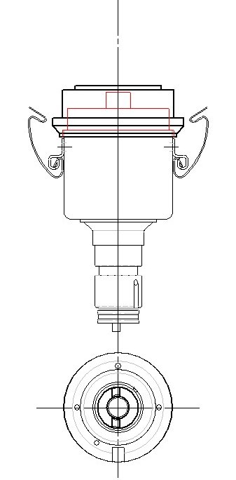
Distributors normally don't run hot.
Even when the engine over-heats, the location of the distributor, up on a relatively cool corner of the crankcase, combines with the heat-flow path and the ratio between the neck of the distributor and its body to cause the distributor to run significantly cooler than the crankcase.
So if you have a hot distributor it's a pretty good sign that something is wrong ...and that 'something' is usually that your engine has been improperly assembled.
Have you got a distributor handy? If you'll examine the neck of the distributor you'll see a hole drilled into the neck just below the groove for the O-ring. A machined trough runs from the hole to the bottom edge of the neck. As you may have guessed, the hole and the trough are there for a purpose, which is to lubricate the shaft of the distributor.
Grab a crankcase and peek down inside the hole where the distributor goes. On the uphill side of the hole -- the side nearest the center-line of the crankcase -- you'll see a small window cast into the side of the hole. When the distributor is properly installed, the trough on the side of the neck of the distributor connects with that window. Of course, that only happens when the engine is properly assembled, since the orientation of the distributor's pinion gear dictates the installed orientation of the distributor. (On the Type I engine, on the pinion gear the slot for the dog-gear on the distributor must be perpendicular to the center-line of the crankcase when the #1 cylinder is at 7.5 degrees before TDC. The smaller segment must be toward the pulley. Note that the alignment is for the static firing point and not TDC.)
Notice that the window opens onto the cast 'shelf' that serves to align the thermal insulator that isolates the fuel pump from the crankcase. The angle at which the distributor is installed and the location of the shelf combine to provide a constant supply of oil for the distributor shaft. Install the distributor incorrectly and you've just shut off the oil to the distributor-shaft bushings. And while the distributor shaft only rotates at half the speed of the crankshaft, it still needs a drop of oil now & then.
-------------------------------------------------------------------------------------------
Back in the Good Ol' Days -- whenever that was -- it was pretty rare to run into an improperly installed distributor. Nowadays it's become pretty common. Why? Mostly because incompetent mechanics install the distributor's pinion gear incorrectly. Which leads to plugging in the distributor so that no oil can get to the oiling trough.
-------------------------------------------------------------------------------------------
Gotta hot distributor? Then there's a high probability it's been running without adequate lubrication. So fix it. Bring the engine to the firing point on #1, pull the pinion gear (you'll need the special puller) and re-install it correctly, making sure to provide the proper number of shims.
How common is this problem? I wish I could say it was rare but about half of the engines I see have the distributor drive-pinion off by one or more teeth. Which is a good reason to send the fellow on his way, at least here in the Peoples Republic of California. Because as soon as you lay hands on the thing you can be held liable for any future problems. Neat, eh? And you wondered why it's so hard to find a good VW mechanic :-)
Fortunately (for me) you don't have to pull the distributor to see that it is mis-aligned. Installing the distributor's drive-pinion incorrectly is good evidence that whoever assembled the engine doesn't know their ass from their elbow, meaning there's liable to be other, less visible problems, such as mis-aligned bearing shells, wonky valve train geometry and even a mis-aligned cam gear -- all of which they will lay on your doorstep since you were the last person to work on the vehicle.
So you smile, praise their paint job, tell them you're too busy right now and wave them on their way.
> Is it always the same set-up? > I have a '59 with the leads different plugged than my '73...
Yes.
I assume the main purpose of the window is to provide lubrication for the upper end of the pinion gear, which uses the parent metal of the casting as a bearing and must be a nice fit in the bore because of that, something you check prior to assembly when blueprinting the crankcase. (A lot of used crankcases fail this test.) It is the orientation of the drilled hole and machined trough on the neck of the distributor that makes it clear they are meant to align with the window.
I've never measured the width of the window in the wall of the distributor bore (it will vary slightly from one casting to the next) but it's an oval which I think is about 5/8" wide on its major axis. The trough on the distributor comes only to the top of the window, meaning it has to be nicely centered to keep from being obstructed due to the oval shape.
Given that the bore is about 27mm in diameter, and that the pinion gear has 12 teeth, I suppose you could be off by a tooth on either side without obstructing the oil channel... assuming a wide and relatively square window. But any greater mis-alignment will drastically reduce the amount of oil getting to the distributor bushings -- or shut it off entirely.
Fortunately, the alignment of the pinion gear is easy to check: First, find a picture of the correct orientation in the factory service manual. (I wouldn't trust Muir; a lot of the drawings are inaccurate.) Bring the engine to the firing point for #1 and simply pull the distributor. On a bug you can look directly down the bore (on a bus you'll probably need an inspection mirror).
-Bob Hoover
PS -- I've received a couple of interesting messages from folks eager to argue about the orientation of the pinion gear. I'm not.
--------------------------------------------------------------------------------------------
>>But this point that Bob brings up is more serious: if the erstwhile type IV > owner installs a spankin'-new SVDA distributor, figures out the wire > re-mapping and congratulates himself on doing right by his ride, he could be > in for a nasty surprise.
I don't consider myself qualified on Type IV's (ie, the '1700,' '1800,' and '2000' engines, to use VW's terminolgy ['Type' actually refers to the chassis.] My post was specific to the '1600' & earlier crankcases (and I'm too lazy to go dig a T4 our from under the bench :-)
But it should be easy enough to check, assuming you're up to your eyeballs in T4 parts. One method is to compare a stock distributor from a T4 to the same thing from a T1. If the groove is in a different location relative to the vacuum can then you may have a problem. Method #2 is examine a T4 crankcase to see if it has a similar window and if it is in the same relative location as on the T1. If the answer(s) is yes, then you've got a problem, since as you've pointed out, the location of the canister on the beetle distributor forces you to install the distributor in a position that will block or reduce the flow of oil to the bushings.
--------------------------------------------------------
As a point of interest, the earliest VW distributors were made of cast iron, fitted with replaceable bronze bushings having a spiral oil channel. I don't recall them having an external oiling groove.
> Isn't the timing for cylinder #3 slightly retarded normally, so that one > would run cooler? Is that not accomplished with the distributor? >
Yes. At least, for all carburetted engines starting with the 1965 model year and continuing until the introduction of the external 'dog-house' oil cooler. The #3 lobe of the distributor was ground with 2 degrees of retardation. Because of the 2:1 ratio between the cam and crank that means #3 will be retarded by 4 degrees. (There's a VW Service Bulletin covering the beginning dates & serial numbers. I assume another was issued when they went back to the unmodified cam but I've never seen it.)
If you're unsure of the provenance of your distributor you should have it checked on distributor testing machine. Or you may check it using a stroboscopic timing light and accurate degree-wheel. Simply transfer the timing light's pick-up to the other three spark plug leads, noting the firing point for each.
The main hazard is that if an early distributor is installed incorrectly the fellow is liable to time the engine using the #3 lobe (ie, directly opposite #1 in the firing order). Which means the other three jugs will now be advanced by four degrees. During hot weather, with the engine under a heavy load, 4 degrees of unwanted advance can result in detonation. And has.
> is there a way i can get the distributor drive gear out without having the > special puller?
(First things first: Start by pulling the fuel pump and removing its push-rod. Now you're good to go.)
On an old (ie, worn) engine you can sometimes extract the pinion gear by driving a hardwood dowel into the recess for the compression spring. Of course, if the dowel breaks off in the hole you're pretty well screwed.
I've used a pair of 'reverse-pliers' (ie, squeezing them causes the jaws to open rather than close) which were designed to extract the broken-off pipe from pop-up lawn-sprinklers. They have hardened jaws which grip the pinion gear in a manner similar to the special tool.
However, I've done it a time or two and this is one of those cases where experience counts. Because the pinion's driver-gear is a spiral (ie, the 'brass gear' on the nose of the crankshaft) the pinion and the crankshaft must be rotated as the pinion gear is extracted. Not a bunch... just a tad. There is a certain feel that tells you when it's coming out okay. Plus, the circular inclined plane that drives the fuel pump often builds up a layer of varnish on its outer edge, making it a tight fit in the upper bore. Here again, there's a certain feel that tells you if all is going well or if you should back off, rotate the thing and try again.
Like riding a bicycle, touch-typing or hitting a fast-ball, once you've done it a few times -- once you know you can do it -- it's really pretty simple. And once you know you can do it you will see other ways to get a grip on the pinion gear.
But the main reason for using the regular tool is that once you've removed the pinion gear you are expected to replace it, and that is one hell of a lot harder to do without the proper tools.
-Bob Hoover
AV - VP Accidents & Icing
.
The accident figures are similar for other VW-powered designs and whatever the actual accident rate, it's too high. It's also largely preventable, in my opinion, at least with regard to engine-related events.
I've seen my share of fouled plugs and fifth-hand Vertex magnetos with fried points. And even attended a couple of Total Idiot tear-downs where we found no evidence of fuel anywhere in the system and a couple with no oil in the engine. (You really should safety-wire the sump plug.)
The real pissers were the cases where we couldn't find anything wrong. There was fuel in the carb, the ignition system provided a spark at the proper timing and all the controls were intact, at least up to impact. In a couple of cases the engine was still in running condition. If that happened once or twice it would fade into the statistical background but when you personally see a dozen or more cases like that it's a strong indication of a fundamental flaw. But one that leaves no obvious clues.
What you do have is the accounts from the surviving pilots; the classic 'loss of power,' or 'the rpm began to drop'. Track that back to the location of the event, dig out the best records you can find for the weather at that particular time & place and guess what you'll generally find? Conditions ideal for the formation of carb and manifold icing.
Any discussion of icing gets you into a matrix of factors but the basics are pretty simple: The vaporization of gasoline is endothermic -- it absorbs heat. It doesn't matter if you're using a carburetor or the latest gee-whiz slide-valve piece of shit, you've got a mini-refrigerator attached to your engine and if the local atmosphere isn't able to provide enough heat to keep the endotherm above the freezing point any water vapor in the air is going to appear as ice.
With a carburetor you can bootstrap yourself into this situation by reducing the throttle. This leaves just a tiny gap between the throat and the throttle plate (usually of brass) and a lip of ice can appear on the down-stream edge of the throttle plate quick like a bunny, even here in sunny southern California. (The oft-repeated claim that slide-valve gas passers don't ice up because they don't have a butterfly valve (ie, throttle plate) is fallacious. Under the right conditions the whole damn slide can ice up.)
That's why we pull on Carb Heat before we begin our let-down.
But you can also get ice in your manifold, even under full-throttle conditions, assuming you have long intake runners that are not provided with any form of supplemental heating. Lycoming routes their runners through the sump. Continental usta say theirs picked up enough heat from the cylinders. Volkswagen vehicles use the exhaust gases from one jug to heat their manifold. And yes, Virginia, your slide-valve Lake, POSA, Aero-Carb or whatever is just as susceptible to manifold icing as a carburetor. So let's forget the 'ice-free' bullshit.
The key point here is that some of the VW engines which suffered the classic 'loss of power' syndrome had no provision of any form for carb heat and all of the others had carb-heat systems incapable of providing enough heat for worse-case conditions.
How much heat is that? About 90*F over ambient, according to the FAA.
Based on experiments I did here at the shop, a carb-heat stove fed by just one cylinder of a 2180 engine couldn't produce a ninety degree rise when passing enough air for the engine. Reduce the throttle, you reduce the amount of air required but you also reduce the amount of heat available. Catch-22. You need the heat from two jugs, not one.
A related part of the problem is that the typical homebuilder's heat exchange isn't very efficient. I know mine wasn't even though I religiously copied the design advocated by the experts of that era - an old screen-door spring wound around the exhaust stack with a muff made out of a couple of tomato cans. (ie, Pietenpol, Leslie Long, et al). Indeed, after a few months out in the weather you generally got more rust out of the thing than hot air.
Pot-scrubbers worked better than door-springs and didn't rust. (ie, those big stainless steel pot-scrubbers; hardware stores usta carry them back in the paint department; you used them for scrubbing walls & woodwork before applying new paint. And for pots too, I suppose.)
Tapping the waste heat from two cylinders is better than using just one. And you can make a better heat exchanger, too. Assuming you know how to weld and are willing to devote a bit of time to it.
I don't have a pat answer for the carb heat problem although I'm convinced that with converted VW's it's one of the few cases where more is better. My current effort in that direction is using a stud gun to weld a bristle of pins to two sections of carbon steel exhaust pipe which will be mounted side by side inside a stainless steel muff and fed by two cylinders. The idea is to produce the best transfer of heat with the least restriction to air flow and I think the idea will work out... eventually :-)
It's worth mentioning that most of my experiments don't work out :-) Not that they're total failures -- you always learn something -- but they are seldom totally successful. What does work is to keep adding what you've learned from the last experiment to your next one. You'll eventually arrive at a system that meets your needs, although it's never as simple & easy as the original concept. Sorta like life, in that respect :-)
I make my heat boxes out of whatever scrap aluminum is available. Riveted construction. Sized for the Tillotson Model X carb (ie, 1-7/8" inlet). Controls are simple Bowden cables. Drawings & photos are included in the HVX files.
-R.S.Hoover
PS - In conjunction with this thread I was asked why all this hot poop I'm handing out hasn't appeared in their favorite aviation magazine. The simple answer is because they don't want to pay for it.
After spending years (in some cases) to develop a suitable solution, such the carb-heat thingee, to convey that information to others in an understandable fashion may require dozens of drawings, photos and illustrations supported by thousands of words of text because in technical writing (which is what I do for a living) it isn't the simplistic straight-line path that's important, it's explaining what to do when things go awry; identifying the potential problems some distant reader might encounter and providing workable methods of avoiding such mistakes and in some cases, of recovering from them.
Package all that in camera-ready copy, send it off to an aviation magazine and if they express any interest at all, they may offer a $100 for your months of effort. If they offer anything at all. Some believe you should give them material for their magazine... which they then sell for a tidy profit.
Old news, really. It's been thrashed out time and again on other newsgroups. Mentioned here in passing because of a couple of messages from folks who were not aware of it. -- rsh
AV - 'Line' Oil
.
Back before Randolph's there was Lyon Paint Co., from somewhere in Ohio (as best I can recall). Lyon was one of the first companies to specialize in AIRCRAFT lacquers and enamels.
Structures fabricated of welded steel tubing were typically given a dose of linseed oil before being sealed by a threaded plug (near the tail), bolted plate (at the front, typically behind the engine mount attachments) or welded plug (all manner of struts; N-strut, cabanes, lift-struts, etc).
Why linseed? Because it is a 'getter' for oxygen; the linseed oil (ie, made by pressing flax seed) plasticizes as it oxidizes (ie, absorbs the oxygen), turning into a thin layer of varnish.
No oxygen means no rust.
So how did plain old-fashioned linseed oil become 'line oil?'
It didn't. It was always LYON oil. Specially refined linseed oil with a neutral pH (ie, neither acidic nor alkaline). Back then, common linseed oil as used for finishing furniture, improving the flowability of oil-based paint and so forth, was never meant to be used on steel and its pH was not a factor when applied to wood.
So Lyon's 'aircraft-certified' linseed oil became the standard for doping the interior of steel tubing. Nowadays, any high quality linseed oil will serve since all are now close to neutral with regard to pH.
Lyon Paint Co. used the head of a lion as their logo. If you'll examine air-race photos from the 1930's you should be able to spot their logo.
-------------------------------------------------
Sealing the interior of welded tube structures assumes the structure can be closed; sealed off from the atmosphere. When that was not the case the interior of the spar, strut or tube was painted, typically with an anti-corrosion paint, diluted about 5:1, applied by flooding (ie, filling and then pouring out) or by 'sponging' -- using several small pieces of sponge tied to a length of marline or rib-lacing cord. The sponges were saturated with paint as they were pulled into the tube and then pulled through.
Sponging was the preferred method since the interior of seamless tubing always has some residue of lubricant used in the forming process. Sponging served to 'brush' the anti-corrosion paint onto the surface. Of course, you couldn't sponge a tube if it had any interior obstructions. Flooding was the preferred method for shorter sections, the paint usually preceded by one or two floods of solvent followed by an air-blast. Such messy little chores often fell upon the shop gopher (which was me, fifty years ago :-)
--------------------------------------------------
The need to protect the interior of the tubing reflects the propensity for mild steel to rust. The standard procedure when repairing or recovering an early fuselage or landing gear was to pull the plugs, usually a socket-head set-screw installed in a weldment, and see if there was any liquid 'line-oil' left inside. Most airframe manufacturers cited how much 'line-oil' was used (usually about a pint) and where to pour it in , after which the fuselage was tilted and rotated, the plug(s) removed and any residue allowed to drain out.
Thanks to a whiff of chromium 4130 is less prone to rusting than 1025 and during WWII many structures did not receive 'line-oil,' although some critical parts such as engine mounts and landing gear yokes were pumped full of dry nitrogen under pressure via a Schraeder valve (think of an industrial-grade tire valve) and fitted with a simple pop-up pressure gauge. Any drop in pressure was good evidence of a cracked weld.
-R.S.Hoover
AV - Oil Temps & Sensor Locations

.
In theory, you may install an oil temperature sensor in any location, so long as the sensor is bathed in an active flow of oil. This is to ensure the sensor reflects any change in the oil's temperature as soon as that change begins to take place. As the Pilot-in-Command your main interest is any anomalous change in oil temperature, rather than the temperature itself.
One reason for our lack of interest in precise quantified temperature data is cost. Calibrated mechanical instruments, certified accurate within a given degree of precision are expensive. When precision accuracy is combined with reliability you’re looking at a very expensive piece of goods. Instruments developed for land-based vehicles aren’t especially accurate but are sufficiently responsive for our needs.
The reason we are less interested in the magnitude of the temperature shown on the gauge is because the temperature of the lubricant varies throughout the engine. That is, you may see a wide variation in oil temps from the same engine, depending on where in the temperature is measured. When using low cost instruments, rather than rely on specific numerical readings we insert the sensor into the active oil flow and by reference to other, more critical parts of the engine that may not allow convenient temperature-sensing, we calibrate the meter to our particular engine, dividing the scale of our meter into colored arcs to show the safe operating range.
For example, the oil temperature gauges installed on some VW industrial engines placed the sensor at the inlet to the oil pump and divided the face of the meter into red, yellow and green arcs and provided no numerical information at all. By comparing the VW system against a 400 degree mercury thermometer borrowed from the chem lab at Modesto Junior College, I found the green arc covered (approximately) 170 to 220 degrees on the Fahrenheit scale, followed by a yellow arc extending up to about 250*F and a red arc beyond that. This seemed rather low until I learned that the oil temperature in the valve gallery was typically a hundred degrees higher than that being sensed at the inlet to the oil pump. Clearly, the intent was to warn the operator to reduce the load on the engine when the valve gallery oil temps exceed 350*F.
----------------------------------------
The How-To information for installing a temperature sensor at the inlet to the oil pump (ie, VW's factory-preferred method) (*) has been posted to the internet numerous times since 1994 and there are a couple of web sites that offer step-by-step photographs of the procedure.
-R.S.Hoover
(*) The VDO instrument cluster offered starting in 1970 (?) was a dealer-installed option and subject to numerous Service Notes over the years due to their often hilariously incorrect readings)
AV - Varnish
.
> > Do you varnish the inside of all the drilled holes and underneath all fittings before assembling wings? <<
Always.
Because a hole exposes the end-grain of the wood it usually receives extra attention, such as blocking the back-side of the hole with your finger and FILLING the hole with diluted varnish, poured from a small can, etc. Wait a few moments then position the can under the hole and remove your finger. (Proper orientation assumed.)
You won't appreciate the need for this until you've removed the fittings from some older wooden structures. Or rather, tried to remove them :-)
Even with cadmium plated AN hardware you'll often find bolts corroded solidly into the wood, fittings deeply etched with rust on their back-side and so forth. The VP's landing gear attachment bolts are especially prone to corrosion due to their location and the depth of wood.
If you want to add a sealant to the shank of the bolt you may find paraffin (white mineral wax) to be a better choice than vanish.
>>Thanks for the reply. I was contemplating using Q-tips to varnish the holes......certainly like your method better.<<
Before Q-tips there were patches.
Traditionally, a 'patch' was piece of cotton fabric about the size of a silver dollar. You made them out of scrap left over from a covering job, or cut them out of tape. For repair work you had doped patches and plain. Fabric-covered aircraft that actually worked for their living were always getting holes poked in them. The typical hole resulted in an L-shaped tear. Small tears, you'd use a curved needle to take a couple of baseball stitches to hold the tear closed then apply a doped patch. (The idea here is that the dope was the same color as the airplane; otherwise you used a clear-doped patch.)
Nothing really new. In Vietnam we used aluminum beer cans and a smear of RTV. (By the Vietnam era most fabric covered control surfaces were Razorback -- fiberglas, rather than cotton.)
-----------------------------------------------
Point is, to varnish a drilling in a wooden structure, if you couldn't flood it with dilute varnish you poked a piece of safety wire through the hole, made a little hook on the end to catch a varnish-soaked patch. Then you used a soda straw, piece of tubing or a pump-can oiler to flood those outta-postion holes, the patch being pulled partly into the hole to plug it... and finally through the hole to 'paint' it.
Some guys used a rib-stitch needle and a triangle of tape; poked a corner of the tape through the eye of the needle, sorta twirled it to make the plug.
And 'tape' means a roll of cotton fabric, two to four inches wide with pinked edges. And pinked edges means.... (this could go on all night)
-------------------------------------------
Kind of an interesting point in all of this, in that while most assembly and re-covering manuals talk about sealing holes in wood, I can't recall any that told you how to do so. The methods I've described above I learned from my dad, an old time A&P, or from other mechanics.
Also note that all the stuff I've mentioned -- safety wire, fabric tape, patches and so on -- is stuff that would normally be available & near at hand if you were working on airplanes. Working in your garage, covering with dacron, if Q-tips are all you got, then usem.
The important point is to provide a good seal inside every hole through wood. Aircraft wood is twelve to fifteen percent water by weight. Softwoods, such spruce, pine, hemlock or fir... the stuff commonly used in aircraft ...like to absorb moisture and does a good job of transporting it from one end of a stick to another, which is why stored wood usually gets its end-grain sealed with wax, tar or paint.
After the wood is used to build something, the last step in the fabrication is to seal the whole surface of the wood. Once you've sealed the wood with varnish or whatever, its moisture content remains fairly stable and if protected from sunlight, it sort of goes to sleep -- it stops aging, or at least, slows down to the point where the process is not apparent to humans. Periodically, such as when we replace the fabric, we re-new the seal of the wood. This isn't unique to airplanes, it is the natural order of things that applies to anything made of wood.
> I think 50/50 is too thin. 90/10 is more like it. The very experienced fellow who painted and/or varnished everything in and on our house told me this.<<
Houses aren't airplanes :-) Experience derived from house painting or furnature building is of little use when it comes to protecting the structure of a wooden airplane.
Airplanes are largely built of softwood. The first coat of varnish should in fact be little more than thinner. The objective is to seal the wood at the microscopic level, which thinned varnish does perfectly well... if you thin it enough. For spruce, fir and pine a first coat of only 25% varnish to 75% thinner is not unusual (ie, ratio of 1:3)
The first coat is allowed to dry until #120 paper produces only a dry white powder with no clogging at all. The sealed surface is then sanded lightly. 'Scuffed' was the old-fashioned term; some times you heard it described as 'dulled' but either definition leads to misinterpretation unless you've seen the procedure being done. It is basically a light but complete sanding with fairly fine paper, after which the surface is wiped down with a clean tack-rag, frequently turned. The finish coat is usually 75% varnish thinned with 25% thinner. (ie, ratio of 3:1) Nowadays I suppose everyone uses White Mineral Spirts as thinner. When using real spar varnish we used turpentine.
The above procedure is valid for the interior structure of wooden aircraft. For the exterior -- wooden struts, gear-legs and tail skegs, the second coat was given an additional sanding; the final coat was full strength varnish, properly laid-on. Varnished exterior surfaces were frequently inspected and renewed as required. Interior structures were sanded & renewed with each re-cover. (Ed. Note: 'Full Strength' might still mean some degree of dilution with thinner, especially if the varnish were old. The reason here has to do with application rather than penetration, in that the varnish must be thin enough to flow-on in a smooth coat.)
A point many overlook is that with airplanes, the finish is supposed to weigh as little as possible. This dictates methods and procedures that are never used with furniture, gun stocks, marine bright-work and so forth, each of which differs from the others to some degree.
As for application of the final varnish coat with a spray gun, while this is commonly done when refinishing props, struts and large panels of fabric(*) or plywood it is seldom used for the interior structure of wings due to the large number of edges, nooks & crannies, for which a brush generally goes a better job.
-R.S.Hoover
(* - At one time varnish was a common finish for cotton & linen fabric.)
Subscribe to:
Posts (Atom)